UReader
Brands
Sign in
Sign up
Newsletter Search Engine
Dates
2025 (205704)
2026 (56633)
2024 (51094)
Business Categories
General
(99712)
Other
(57034)
Home
(21825)
Fashion
(20866)
Electronics
(16522)
Literature
(11163)
Sports
(11025)
Art
(8467)
Machinery
(4992)
Health
(4649)
Food
(2899)
Country
GLOBAL
(36080)
CO
(19570)
NL
(17160)
AU
(16672)
GB
(14791)
NZ
(14718)
US
(13488)
BE
(13119)
DE
(8874)
FI
(8534)
CL
(7627)
CA
(7423)
PL
(7278)
RO
(7115)
ES
(6735)
HU
(6458)
ZA
(6393)
IL
(5943)
AR
(5908)
DK
(5620)
FR
(5269)
SK
(5202)
BR
(5140)
HR
(5049)
IT
(4967)
CZ
(4633)
PT
(4472)
SE
(4440)
IE
(3820)
GR
(3804)
NO
(3763)
SG
(3121)
CH
(3038)
BG
(2902)
RU
(2596)
MY
(2266)
UA
(2238)
MX
(2144)
JP
(2114)
AT
(2114)
PE
(1842)
RS
(1753)
TR
(753)
VE
(747)
IO
(665)
ID
(589)
TW
(584)
PK
(574)
IQ
(539)
HK
(497)
MA
(476)
PH
(434)
TV
(407)
AE
(315)
TH
(247)
KW
(188)
KP
(108)
VN
(54)
EG
(42)
IN
(8)
KZ
(4)
MD
(2)
NU
(2)
LT
(1)
BA
(1)
LK
(1)
Total 313431 mails
mytopia
AU
·
2026-6-9
⚡ Blink & You’ll Miss It 🧨
costco
AU
·
2026-6-9
Looking for Peace of Mind and Value to Match?
1sale
US
·
2026-6-9
🎁 A Few Amazon Finds We Couldn’t Stop Thinking About
thesleepstore
NZ
·
2026-6-9
MONSTER SALE is back!
outspot
DE
·
2026-6-9
Sommerhut
flowerstore
PH
·
2026-6-9
The ube gifts everyone's been waiting for 💜
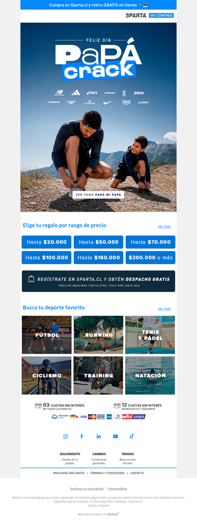
sparta
CL
·
2026-6-9
Encuentra el regalo para tu papá crack 😍
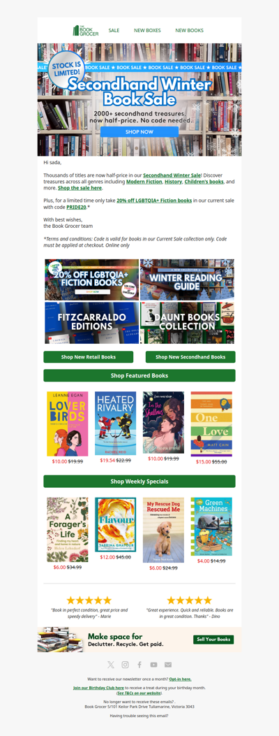
bookgrocer
AU
·
2026-6-9
Massive Secondhand Winter Sale on now🤩📚
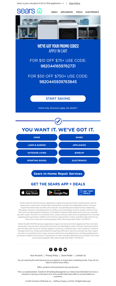
sears
GLOBAL
·
2026-6-9
Reminder: Use your $50 off!
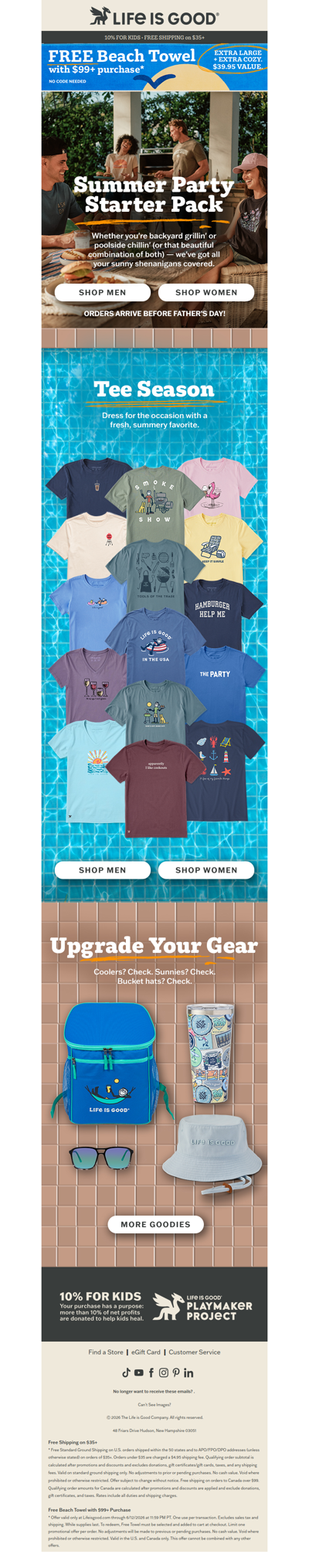
lifeisgood
US
·
2026-6-9
Pool Parties. Barbecues. T-Shirts.
toypanic
MY
·
2026-6-9
ToyPanic Preorder & In-Stock - 09/06/2026
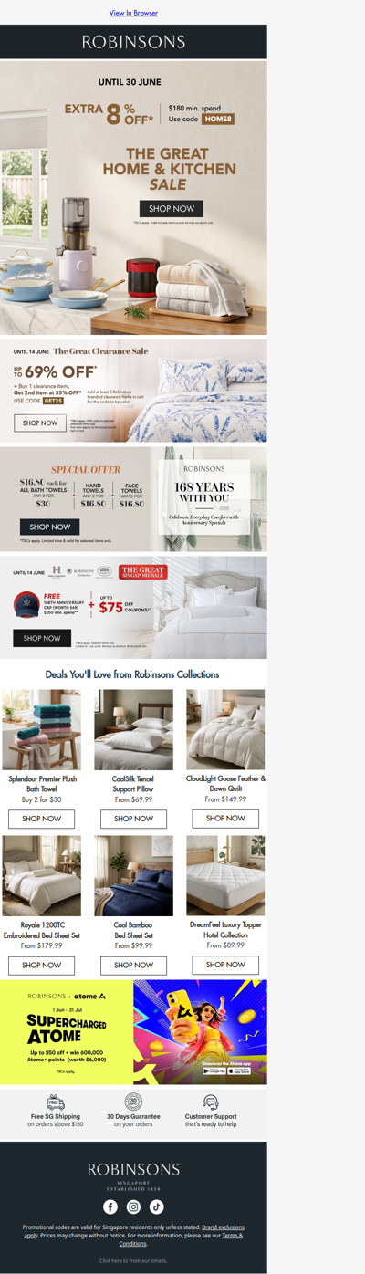
robinsons
SG
·
2026-6-9
Extra 8% Off Home & Kitchen Favourites
1
2
3
4
5
©2024 UReader
Home
Brands
Marked Emails
Followed Brands
Privacy Policy & User Agreement